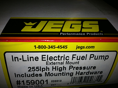


So anyone that's done this stuff before, would instantly notice that I purchased an unusable fuel pump for this application. I purchased a fuel pump for a carbureted engine. All this type of pump needs to do is produce enough force to overcome the weight of the fuel in the line, and the inertial effects of the vehicle it is installed in, to fill the bowl of the carb. The carburetor will take care of getting the fuel into the engine, allowing the engine to pull in a metered amount of fuel.
In a fuel injected engine, the fuel is forced into the engine at computer prescribed times. Thus, the fuel needs to be delivered at much higher pressures. The first pump I bought had more than enough flow (any electric pump would for my application) but only around 1-2psi of pressure. I need 43.5 psi of fuel pressure normally aspirated, plus I need to add my boost pressure to that as well; this keeps the math linear for the metered amount of fuel (by opening the injector for a specified time period). The pump I found was the lowest flow-for-the-money I could find. Actually, my friend, and Camaro expert (always in a magazine) Roy Fender, suggested this unit: Jegs Fuel Pump 159001
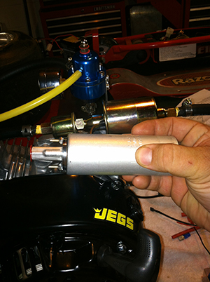
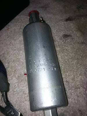
Here are some images of the new FP installed. It is plumbed in the same way the old pump was, as illustrated on the last page, this one is just mounted using different holes on the engine casting. This pump also came with a neoprene "coozy", I suppose if people are running alcohol it can condensate, or perhaps it's just to keep the fuel as cool as possible. I'm sure somebody reading this post will know. Please email me if you know!
I am currently attacking the RPM sensor assembly. The idea is that not only does the computer need to know the RPM to calculate proper fuel amounts to deliver, but the speed of an engine can vary greatly within one revolution. This means simply counting each revolution per time is out. We need to be more accurate than that. This is why cars, motorcycles, etc. use trigger-wheels. The more teeth on the trigger-wheel, the more accurate (the more updates per revolutions). The trigger-wheel I purchased came from DIY-Auto-Tune and is a 36-1 (36 tooth -minus 1). This means there is a tooth every 10 degrees (10 degrees times 36 teeth = 360 degrees) except for a space where a tooth should be, but is missing. The space is used by the computer to calculate where the actual position of the crank is. As this wheel spins, the teeth come into close proximity to a Hall effect sensor. I used a Hamlin 55505 Digikey and Mouser usually keep them in stock. The output operation is the same as the sensor we used for the cam position sensor (utilizing a pull-up resistor, except it is internal, so we do not have to wire one in). However, it becomes important to look at the switching speed of the sensors you choose when you are looking at a sensor for a trigger-wheel because, in our case, they are switching at the engine RPM times 36 (the number of teeth on the wheel). Switching speed is usually given in units of time or by frequency. I do not believe this motor will spin to 9,000 revolutions per minute, but let's use it for our calculations. With a maximum RPM of 9,000 times 36 trigger teeth per revolution equals = 324,000 switching cycles per minute / 60 = equals 5,400 switching events per second, or, 5.4 KHz. Our sensor has a maximum switching frequency of 15 KHz, so we will be more than OK.
I found the 3/4" hub at Northern Tool, it is obviously way too thick to use on the axel, leaving no room for the centrifugal clutch. I will find some way to machine it down after I decide how to fix it to the trigger-wheel.
I also found an interesting internet tidbit the other day. I'm not the first to attempt this project! Check out: Mark Muzzin's website and his youtube video: Here .
Yet another update: I have found another site attempting this project in the mid 2000's. found here: http://www.turbokart.com/turbo_exciter.htm . It looks like this guy got his running too. I cannot find any videos of the kart on the road and accelerating, but there is a video of the engine starting. There is a lot of good information on this site. He went the carbureted route, so all information does not apply. Interesting non-the-less.
So I found a hub on ebay (3/4" I.D. and keyed) for a ridiculous $75.00 or best offer. I offered 20 bucks, and bingo I won it! I had it faced off (machined), taking about 1/2 an inch off the face to get it a little thinner (cost me $15 cash). When I got the new hub home I ran a tap through it to clean up the threads, painted the trigger wheel and assembled the new component.
so that the hub-trigger wheel assembly would go together, I needed to pre-cut a piece of key and tap it into place in the hub.
Turbo Predator Table of Contents